DRILLING & FASTENING
SDS-PLUS, SDS-MAX AND DRILL SHANKS
SDS is a shank and chuck system, not a screwdriver tip profile.
8 MIN READ
IN THIS GUIDE
SHANK, CUTTING HEAD AND DIAMETER ARE DIFFERENT THINGS
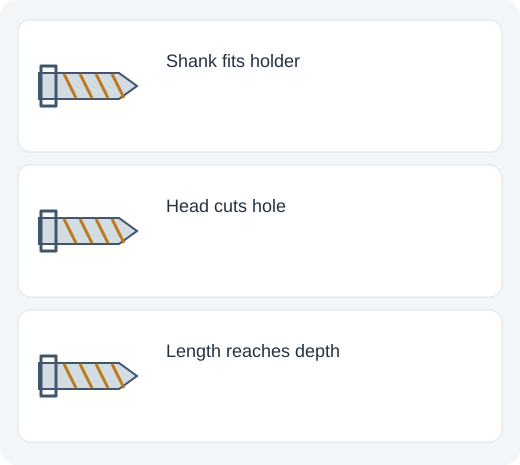
The shank is the end that fits into the tool. The cutting head is the end that works on the material. A drill bit marked 12 mm can have a 12 mm cutting diameter and a shank with a completely different diameter. Never choose the holder from the hole size alone.
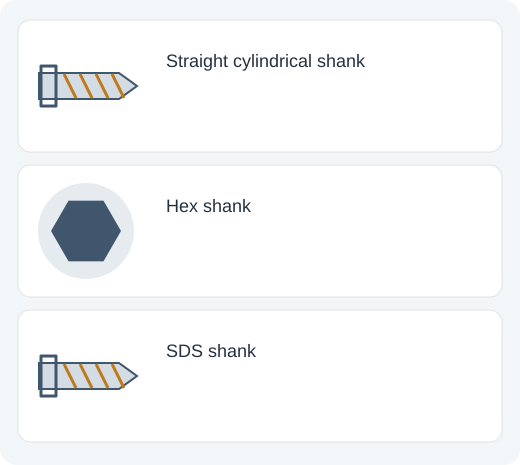
A smooth round shank is commonly held in a three-jaw drill chuck. A hex shank can be gripped by a compatible chuck or holder. SDS shanks have grooves for a matching rotary-hammer holder. The shapes are interfaces, not interchangeable brand names.
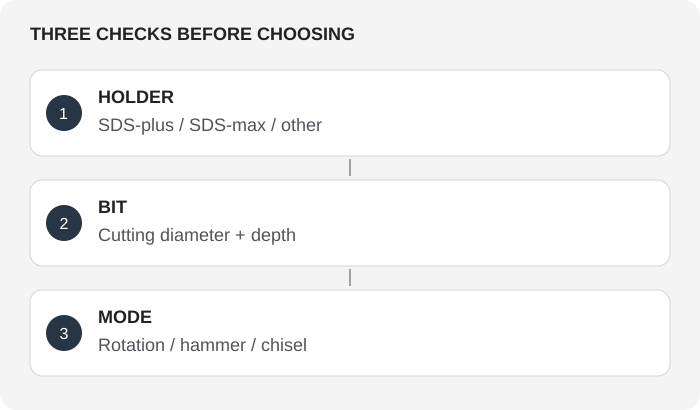
The correct first question is “Which holder does my tool have?” The second is “Which bit diameter, working length and cutting head does this job require?” Those two checks prevent many mistaken accessory purchases.
WHY SDS BITS MOVE IN THE HOLDER
A rotary hammer delivers blows along the bit’s axis. The SDS connection holds the bit against coming out while allowing controlled axial movement. Drive grooves transfer rotation; retaining grooves work with the holder’s locking elements. This movement is part of the operating principle, not automatically a loose or defective chuck.
An SDS holder does not clamp the shank like a normal three-jaw chuck. On a typical holder, you insert the compatible bit until its retention mechanism engages, then check that it cannot simply pull out. Use the exact insertion, release and lubrication instructions for the model.
The hammering mechanism and the bit must work together. A masonry bit with a smooth shank is not automatically an SDS accessory. Likewise, a grooved SDS bit is not intended to be clamped into an ordinary impact driver.
SDS-PLUS
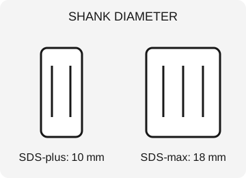
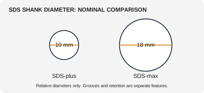
SDS-plus has a nominal 10 mm shank and four grooves: two open drive grooves and two closed retaining grooves. It is common on compact and medium rotary hammers. The shank diameter stays the same across many cutting diameters, which is why a 6 mm and a 16 mm SDS-plus masonry bit can fit the same holder.
SDS-plus is often used for masonry holes, suitable concrete drilling and light chiseling when the tool supports those modes. “Often” is not a working-capacity specification: check the tool’s recommended drilling range, permitted accessories and duty cycle.
Older SDS and SDS-plus interfaces are closely related, but an accessory must still match the tool instructions. Regional or older names can be confusing. Read the actual holder designation instead of assuming that every product called “SDS” uses the same connection.
SDS-MAX
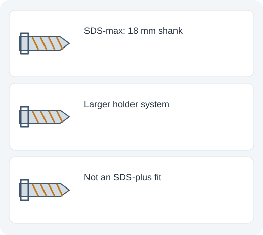
SDS-max has a nominal 18 mm shank with five grooves: three open drive grooves and two closed retaining grooves. It is commonly found on larger rotary and demolition hammers used for heavier drilling and chiseling.
The larger interface can support different tool and accessory demands, but it does not make an SDS-max tool automatically right for small precision holes. Weight, vibration, tool capacity and the workpiece all matter. A smaller tool can be more manageable for repeated overhead work.
SDS-max and SDS-plus do not fit directly into each other’s holders. An adapter, where approved, does not increase the smaller bit’s strength or the host tool’s permitted operating capacity. Do not treat an adapter as proof that every mode and accessory combination is acceptable.
OTHER SHANKS AND HOLDERS
Spline-drive rotary hammers and older SDS-top tools use other interfaces. A spline shank may look superficially similar to a grooved SDS shank but has different engagement geometry. Match the exact tool specification.
Some rotary hammers have an interchangeable standard chuck for ordinary drilling in wood or metal. That chuck is generally used with rotation-only mode when the tool instructions permit it. A normal chuck and ordinary bit are not automatically rated for the tool’s axial hammering mode.
A 1/4-inch hex impact-driver holder is another interface entirely. Its shape, retention and operating loads differ from both SDS and a square-drive socket connection. Equal-looking numbers on different interfaces do not establish compatibility.
DRILLING BITS, CHISELS AND TOOL MODES
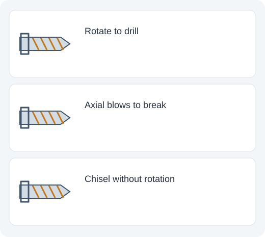
A masonry drilling bit removes material by rotating and hammering. Its carbide cutting head and flute geometry matter to performance. Different cutting-head designs are intended for different tasks; a higher cutter count is not a universal guarantee of better work in every material.
A point chisel concentrates blows; a flat chisel removes material across a wider edge; a tile or scaling chisel uses a wider geometry for surface work. A chisel is not a drilling bit. Use a tool and mode that support chiseling without rotation, and set any chisel-position function as directed.
Many rotary hammers have rotation-only, rotary-hammer and hammer-only modes, but not every model has all three. Choose the mode before work. Follow the instructions for any mode changes; forcing a selector while the mechanism is under load can cause damage.
CHOOSING DIAMETER, DEPTH AND LENGTH
Choose the hole diameter required by the anchor or fastener instructions. An anchor specification is more reliable than a guess based on the fastener’s outside appearance. For installations with defined loads, diameter, embedment, edge distance, hole cleaning and the base material are part of one system.
Working length is the usable drilling depth; overall length also includes the holder end. A long bit reaches farther but may be harder to control. Do not buy by overall length when the required hole depth exceeds the actual working length.
Use a suitable depth stop or another approved method to control depth. Before drilling into a building surface, check for wiring, pipes and other concealed hazards. In concrete, encountering reinforcement changes the job: do not assume that drilling through it is permitted merely because the bit can continue cutting.
DUST, INSERTION AND UPKEEP
Concrete and masonry drilling can create respirable silica dust. Use suitable extraction and protective measures for the work and applicable requirements. A small visible dust cloud does not tell you the actual exposure level.
Keep the shank and holder clean. If the manufacturer requires shank grease, use the specified type and amount; excess grease can attract contamination. A dirty or worn shank can affect retention and operation. Disconnect power before accessory changes and check retention after insertion.
Inspect the cutting head and shank. A damaged head, bent body or worn retaining geometry is a reason to replace or service the appropriate part. Let a hot accessory cool before handling it, and do not use a bit as a lever to free stuck material.
QUICK SELECTION EXAMPLE
Suppose your tool has an SDS-plus holder and the anchor instructions require a 10 mm hole to a defined depth. Choose a 10 mm cutting diameter, SDS-plus shank and sufficient working length. Confirm the bit is suitable for the base material and the tool’s drilling capacity.
Now suppose you need to remove tile. The same holder may accept an appropriate chisel, but the tool must support hammer-only operation. Holder compatibility alone does not establish that the accessory or mode is right for the work.
If a listing only says “fits hammer drill,” do not assume SDS compatibility. A conventional hammer drill with a three-jaw chuck and a rotary hammer with an SDS holder are different tool designs.
CHOOSING A BIT FOR AN ANCHOR INSTALLATION
Start with the anchor instructions, not with a bit that happens to fit the drill. The anchor specifies acceptable substrate, hole diameter, drilling depth and preparation. A nominal hole diameter is the cutting diameter at the bit head; it is not the SDS shank diameter. Select the required cutting size in the holder system used by your rotary hammer.
Check usable length separately from overall length. A bit advertised with a long overall dimension includes the insertion end and may not provide the required drilling reach. The fluted working part must also evacuate dust effectively. If the hole approaches the useful flute length, confirm that the bit and drilling method are approved for that depth rather than burying the accessory past its effective cutting section.
Use the mode and dust-control method appropriate to the bit, tool and anchor system. Some concrete drilling applications require special consideration of reinforcement, substrate condition or installation approval. Hitting steel reinforcement is not a reason to force a masonry bit through it without checking whether the anchor location and drilling method are permitted.
After drilling, follow the specified cleaning sequence. Dust left in an anchor hole can change installation performance; a visually open hole is not necessarily a prepared hole. Depth stops, extraction accessories and cleaning tools help, but they must be suitable for the exact anchor and hole. The bit holder interface alone establishes none of these installation requirements.
RECOGNIZING HOLDER FIT AND INSERTION PROBLEMS
An SDS accessory is designed to move axially while being retained. This movement lets the hammer mechanism act on the accessory; it is not equivalent to a conventional drill chuck slipping. A small amount of expected movement should be distinguished from damaged retention, a worn shank or an accessory that can come out without the release mechanism being operated.
With the tool isolated according to its instructions, inspect the insertion end for burrs, heavy contamination or damage. Clean it using the manufacturer’s procedure and apply only the specified lubricant if the holder requires it. Excess or incorrect lubricant can attract abrasive dirt. A bit that requires unusual force to insert deserves inspection rather than being hammered into the holder.
An adapter can change what an accessory connects to but does not make all operating modes safe. A conventional chuck adapter may be intended for rotation-only drilling, with hammer action explicitly prohibited. Read the adapter’s instructions and the rotary hammer manual together. Do not infer permission from the fact that the adapter locks into an SDS socket.
If you own SDS-plus and SDS-max tools, store and label their accessories separately. The different nominal shank diameters and groove systems are a clear compatibility boundary. Cutting diameter, brand and intended material can overlap between the families, but that does not make the insertion ends interchangeable.
VISUAL REFERENCE ATLAS
AT A GLANCE
Illustrations explain the principle. They are not actual-size templates or precision fit drawings.
| System | Nominal shank diameter | Common application |
|---|---|---|
| SDS-plus | 10 mm | Compatible rotary hammers |
| SDS-max | 18 mm | Larger compatible rotary hammers |
| Round / straight shank | Varies | Matching three-jaw chuck |
| 1/4-in hex | 6.35 mm across flats | Matching hex holder |
REFERENCES
General reference material. For an exact model, use its manufacturer’s specifications and instructions.
Drill bit shank