DRILLING & FASTENING
DRILL BITS FOR DIFFERENT MATERIALS
Match the working geometry and material application before choosing a shank.
8 MIN READ
IN THIS GUIDE
START WITH MATERIAL AND HOLE PURPOSE
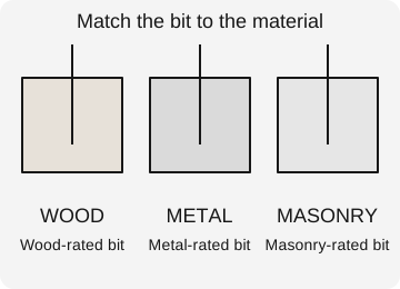
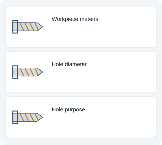
Choose a drill bit for the material first: wood, metal, masonry, tile, glass or another specific substrate. Then choose diameter, depth, hole finish and holder format. A bit that fits the tool can still be completely wrong for the material.
A hole for a structural anchor has different requirements from a cable pass-through or a pilot hole for a screw. The required diameter and preparation should come from the fastener, fitting or assembly specification, not a guess based on appearance.
Consider hidden layers. A wood panel may cover metal framing; a tiled wall may contain masonry, waterproofing, wiring or pipes. Identify the actual workpiece and concealed hazards before drilling.
WOOD BITS
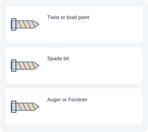
Brad-point bits have a center point and cutting features suited to accurate positioning in wood. Twist bits can also drill suitable wood, but may enter less cleanly or wander depending on the setup. Clamp the work and use backing where a clean exit matters.
Spade bits remove material quickly in suitable applications but may leave a rougher hole. Auger bits are useful for appropriate deeper wood drilling and require a tool capable of the load. Self-feed designs can pull aggressively, so grip, support and tool limits matter.
Forstner bits can make controlled flat-bottomed holes and overlap suitable existing holes when properly used. Large diameters require suitable speed, feed, work support and tool capacity. Do not assume that a bit with a small shank creates a light drilling load.
METAL TWIST BITS
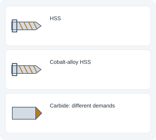
High-speed steel, or HSS, is common for many metal-drilling tasks. Cobalt-alloy HSS is useful where higher heat resistance is important, including suitable stainless-steel work. “Cobalt” usually describes an alloyed cutting material, not a bit made from pure cobalt.
Carbide can provide excellent wear and heat resistance in an appropriate rigid setup, but is more brittle and is not automatically the best choice for every handheld job. Material, geometry, feed, coolant and stability work together.
For a clean starting point, use an appropriate locating method and secure the workpiece. Thin sheet can grab or distort as the bit breaks through. Backing, suitable geometry and controlled feed help; never hold small metal pieces in a way that lets them spin in your hand.
STEP BITS AND HOLE SAWS
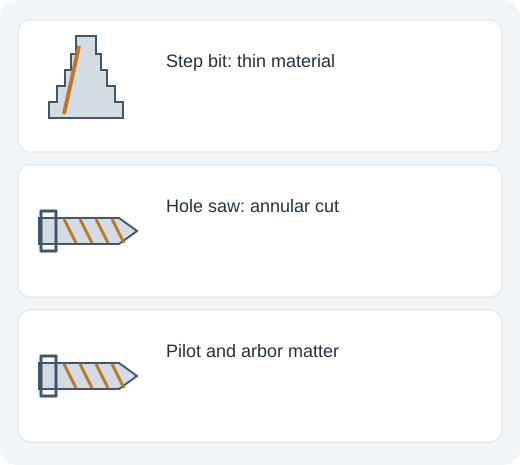
A step bit provides several increasing diameters on one tool and is especially useful for suitable thin sheet. Each step has a working length, which limits the material thickness that can be cut at that diameter. The largest number on the bit is not a guarantee for thick plate.
HSS and cobalt-alloy step bits can be useful for different metal jobs. Coatings can improve a particular design’s performance, but do not change a unsuitable base material or geometry into a universal solution. Match the bit’s material and thickness rating to the work.
Hole saws cut a ring rather than removing the entire hole as chips. Check cutting material, arbor, pilot bit, depth and the tool’s capacity. Large hole saws can produce substantial reaction torque, especially when they catch.
MASONRY AND CONCRETE BITS
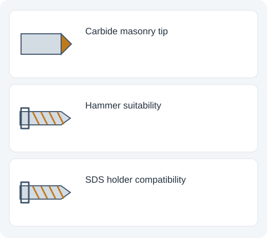
Masonry bits commonly use carbide cutting tips. A conventional hammer drill may use an appropriate smooth-shank masonry bit. A rotary hammer uses a matching SDS or other specified interface. Shank fit and operating mode must both be correct.
Concrete, brick, block and stone are not identical materials. Their strength, voids and reinforcement can affect the method. For anchor installation, follow the stated hole diameter, depth, cleaning and embedment requirements.
Use suitable dust control for silica-containing materials. If the bit encounters reinforcement or a concealed service, stop and assess the work. A bit’s ability to continue cutting does not establish that drilling through the obstacle is allowed or structurally appropriate.
TILE, GLASS AND HARD FINISHES
Tile and glass require accessories intended for the specific material. Spear-point and diamond designs have different applications and operating instructions. Porcelain can be much harder than some ceramic tile, so a generic “tile bit” label is not enough.
Follow the bit’s requirements for cooling, starting method, speed and dry or wet use. Do not apply hammer mode to fragile finishes unless the specific method and accessory call for it. Once through a surface layer, the underlying material may need another bit and mode.
Support the work and plan for the exit side. A clean entrance does not guarantee a clean exit. Cracking can come from heat, unsupported material, excessive pressure or an unsuitable bit, not only from dullness.
SPEED, FEED, COOLING AND CHIPS
Larger cutting diameters generally require lower rotational speeds for a given material and cutting-speed target. A suitable speed depends on bit material, work material and diameter. Use the bit manufacturer’s guidance instead of one universal RPM rule.
Feed is how quickly the tool advances into the material. Too little feed can rub rather than cut; too much can overload, catch or break the bit. In some metals, repeated rubbing and heat can contribute to work hardening. Cutting fluid, where appropriate, affects cooling and lubrication.
Clear chips using the suitable drilling technique. Deep holes may require controlled withdrawal to remove chips, but the exact method depends on the bit and material. Packed flutes raise friction and heat. Stop safely before touching or clearing swarf.
DIAMETER, LENGTH AND HOLDER CHECKS
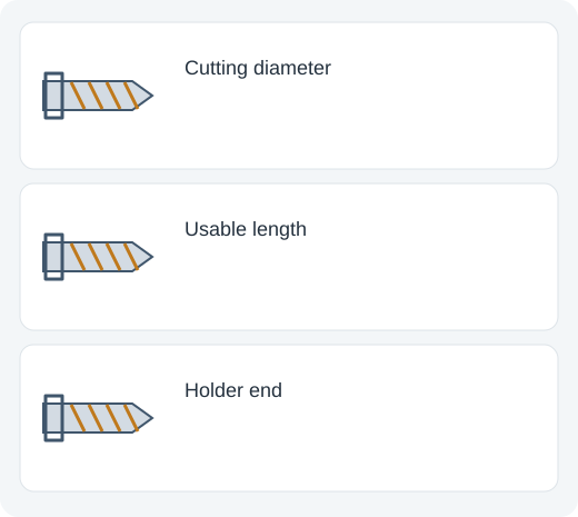
Cutting diameter determines nominal hole size; actual hole quality also depends on runout, setup and wear. Overall length includes the shank, while working or flute length determines usable reach. Choose enough working length without unnecessary flexibility.
Round, reduced, hex and SDS shanks have different holder requirements. A reduced shank makes a large bit fit a smaller chuck; it does not increase the drill’s capacity. A hex shank alone does not prove impact suitability.
Check the drill’s recommended capacity and use the side handle where required. Large bits and hole saws can create high reaction loads. The tool, accessory and workholding should form a suitable system.
SELECTION EXAMPLE AND TROUBLESHOOTING
For a small hole in mild-steel sheet, choose a metal-rated bit or suitable step bit for the thickness and diameter, secure the sheet, and follow speed and lubrication guidance. For a concrete anchor, choose the specified masonry diameter, matching holder and required drilling and cleaning process.
If the bit squeals, smokes, barely cuts or creates excessive heat, check sharpness, speed, feed, cooling and suitability. If it wanders, check starting method, rigidity and runout. If it grabs at breakthrough, reassess support and geometry.
Do not solve every problem by increasing pressure. A dull or unsuitable accessory can overload a perfectly adequate drill. Correct material, geometry and setup matter more than a premium label alone.
UNDERSTANDING THE CUTTING EDGE, CHIP AND HEAT TOGETHER
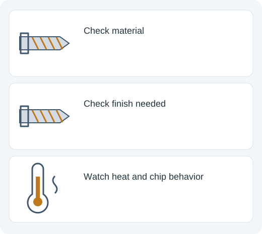
A drill bit removes material by making chips at its cutting edges. The flute provides a path for those chips to leave the hole. If chips cannot escape, friction and heat can increase while cutting becomes less efficient. Greater operator pressure is not necessarily the cure: it can worsen loading, damage the edge or cause the bit to catch.
The same rotational speed produces a higher cutting speed at the outer edge of a larger-diameter cutter. This is why speed recommendations normally depend on both workpiece material and cutter diameter. Use the cutter manufacturer’s guidance for the actual bit material, coating and application; a universal RPM number ignores important differences.
Feed should allow the cutter to work without overloading it or rubbing ineffectively. Too little feed can promote rubbing and heat; too much can chip an edge, stall the tool or distort the workpiece. Observe chip behavior and follow a method suitable for the material. Stainless steel, thin sheet, wood and concrete each require different reasoning.
Cooling and lubrication are application-specific. A fluid suitable for metal cutting is not an automatic choice for masonry, electrical equipment or a battery-powered tool’s housing. Apply any cutting fluid only as permitted for the cutter and workpiece, and manage chips, dust and electrical exposure according to the equipment instructions.
CHOOSING BETWEEN A TWIST BIT, STEP BIT AND HOLE SAW
A twist bit can make a cylindrical hole through a suitable material within its cutting length. A step bit provides several diameters on one stepped body and is commonly useful for thin sheet. The usable thickness at a selected step is limited by that step’s cutting geometry. A hole saw removes an annular ring and usually uses an arbor and pilot arrangement.
For a hole in a thin metal enclosure, compare the required diameter, sheet thickness, edge quality and access. A step bit may offer controlled diameter changes, while a hole saw can suit a larger opening if the arbor, pilot and cutter are appropriate. Neither choice is determined by the tool’s drill/driver label alone.
For deeper solid material, check cutting depth and chip evacuation rather than treating a step bit’s largest printed diameter as a universal drilling capacity. A hole saw also has a working depth and requires a method for handling the cut plug and clearing chips. Confirm that the tool can operate the cutter within its recommendations.
Before buying, verify the workpiece material approval, cutting dimensions, shank or arbor connection and operating conditions. A cobalt-alloy substrate can help resist heat in some metal applications, but it cannot make an unsuitable step geometry work through arbitrary thickness or prevent a poorly supported cutter from breaking.
VISUAL REFERENCE ATLAS
AT A GLANCE
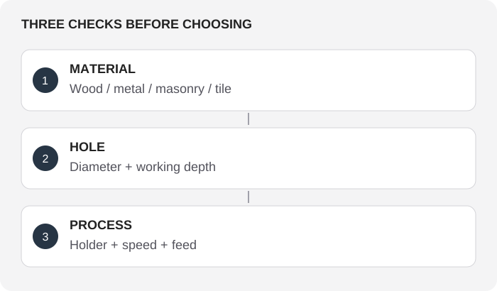
Illustrations explain the principle. They are not actual-size templates or precision fit drawings.
REFERENCES
General reference material. For an exact model, use its manufacturer’s specifications and instructions.
Drill bit