ELECTRICAL & LOW VOLTAGE
RJ45, MODULAR PLUGS AND CRIMPING TOOLS
Match the plug, cable construction and connector-specific tool.
7 MIN READ
IN THIS GUIDE
RJ45 AND 8P8C TERMINOLOGY
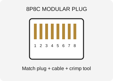
The plug commonly called RJ45 in Ethernet work is usually an eight-position, eight-contact modular connector, or 8P8C. RJ45 has a more specific historical registered-jack meaning, but the common name is widely used in product listings.
For practical selection, identify the exact plug, cable type, conductor construction and intended wiring system. An Ethernet-looking plug does not tell you whether it suits solid conductors, stranded conductors, a particular cable diameter or a shielded assembly.
A connector’s outer shape is only part of its compatibility. Contacts and cable retention must suit the cable. Use the plug manufacturer’s cable range and termination method rather than assuming that every 8P8C plug fits every network cable.
CABLE CATEGORY AND CONSTRUCTION
Category labels such as Cat5e, Cat6 and Cat6A describe performance requirements for suitable cabling systems. Actual performance depends on cable, connectors, installation and testing together. A plug marked Cat6 does not upgrade an unsuitable cable or damaged installation.
Solid and stranded conductors have different construction. Plugs may be designed for one or both within a stated range. Wire gauge, insulation diameter, overall jacket diameter and internal arrangement can affect fitting and contact engagement.
Shielded cables and connectors require a compatible grounding and bonding arrangement for the system. A metal shell is not a reason to assume the complete installation is correctly shielded. Follow the cabling design and connector instructions.
T568A AND T568B PIN ORDER
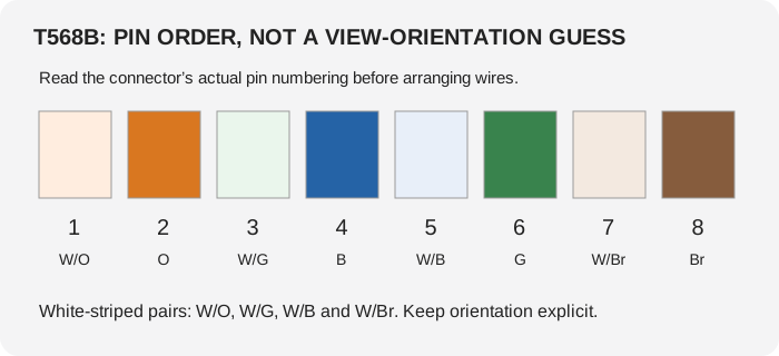
T568A and T568B are common pair-to-pin arrangements. Keep a clear connector orientation when reading a diagram: an opposite viewing direction reverses the apparent left-to-right order. Never copy wire order from a photo without confirming pin numbering.
For T568B, pins 1 through 8 are white/orange, orange, white/green, blue, white/blue, green, white/brown and brown. For T568A, they are white/green, green, white/orange, blue, white/blue, orange, white/brown and brown.
A standard straight-through termination uses the intended same arrangement at both ends. Use the project’s specified convention consistently. Pair membership matters as well as simple continuity; a split pair can appear continuous on a basic check while causing performance problems.
PASS-THROUGH AND CONVENTIONAL PLUGS
A pass-through plug lets conductors extend through the front during preparation, making order easier to inspect. It requires a tool and process that correctly crimp and trim the conductors for that plug. A conventional plug keeps prepared conductors inside the connector.
Pass-through is not automatically better for every environment. Plug compatibility, conductor trimming and manufacturer instructions matter. Exposed or poorly trimmed conductor ends can create termination problems.
Some plugs use load bars or other internal arrangements. Prepare and assemble them according to their instructions. A crimper that closes the contacts does not necessarily provide the correct retention or trimming function for another plug design.
STRIPPING, TRIMMING AND CRIMPING WORKFLOW
Identify the cable and compatible plug first. Strip the jacket without damaging conductor insulation. Keep pair untwisting and preparation within the connector’s requirements. Arrange the conductors in the selected pin order and verify orientation before trimming or inserting.
Seat the conductors and jacket as required. Jacket retention should work on the jacket rather than relying only on individual conductors. Use the matching crimper and complete its intended cycle.
Inspect the termination for seating, order, contact engagement and strain relief. Do not reuse a one-use plug merely because it appears to close a second time; follow the connector’s specified reuse limits. Test the completed link rather than relying on appearance alone.
PUNCH-DOWN AND FIELD-TERMINATION CONNECTORS
Permanent cabling commonly uses suitable jacks or patch panels rather than plugs at every fixed cable end. Insulation-displacement contacts use a defined termination system and tool. Blade types and termination formats must match.
Some field-termination plugs have a different assembly method from ordinary modular crimp plugs. They may be designed for particular cable constructions and use dedicated components. Do not assume a standard RJ45 crimper is needed or appropriate for all of them.
Choose the termination around the installation design, cable and connector specification. The tool follows that choice, not the other way around. A versatile toolkit still needs the correct blades, dies and compatible connectors.
CONTINUITY, QUALIFICATION AND CERTIFICATION
A basic continuity tester checks connections such as opens, shorts and pin order, depending on its capabilities. It does not necessarily verify that the link meets a category performance specification. Some inexpensive testers also cannot reliably detect split pairs.
Qualification tools assess whether a link supports certain applications or performance levels within their design. Certification instruments perform the defined measurements needed to judge compliance with a cabling standard and produce appropriate reports.
Choose testing depth for the job. A continuity result can be useful troubleshooting evidence, but it is not the same as a certified Cat6A channel. An installation can have correct wire order and still fail because of length, pair handling, components or interference.
POE AND COMMON FAILURE PATTERNS
Power over Ethernet adds requirements involving current, contact resistance and compatible equipment. Poor terminations can cause heating or intermittent behavior. Use components and installation practices intended for the system.
Intermittent links can come from damaged cable, poor contact engagement, excessive untwisting, unsupported strain or the wrong plug for the conductors. Diagnose the complete link rather than repeatedly recrimping one end without evidence.
A link that works at a lower speed but not at a higher one may have a pair or performance problem. A network device’s link light is not a complete cabling test. Test with suitable equipment and compare against the installation requirements.
BUYING AND FIELD-WORK CHECKLIST
For a crimper, check supported connector formats, pass-through trimming if needed, die compatibility, ratchet operation and physical access. For a stripper, check cable range and control of cutting depth. For a tester, check what it actually measures.
Carry connectors suitable for the cables you service, not just one generic plug bag. Inspect tools for worn blades and damaged dies. Disconnect and handle circuits according to the system’s requirements; low-voltage networking still includes powered equipment and installation hazards.
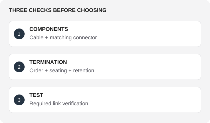
Before closing the job: confirm cable and connector compatibility, wiring arrangement, strain relief, labeling and the required test result. A neat-looking plug is the beginning of verification, not the end.
FROM CABLE SPECIFICATION TO A CORRECTLY TESTED TERMINATION
Read the cable’s construction before choosing a plug: conductor gauge, solid or stranded conductors, insulation diameter, overall diameter, shielding and category. A plug listed for one combination may not suit another. A physically similar 8P8C housing does not establish that its contacts and strain relief can terminate the cable correctly.
Choose the connector and the corresponding termination tool as a matched system. Pass-through plugs may require a cutting feature that trims conductors as intended, while conventional plugs depend on correct conductor length before insertion. Some field-termination connectors use a different process entirely. Do not assume that any crimper labeled RJ45 performs every termination method.
Keep conductor pairs organized and preserve the twist as close to the termination as the connector instructions require. Insert conductors in the specified T568A or T568B order with the correct viewing orientation. Capture the cable jacket with the intended strain relief; gripping only the individual conductors does not provide the same mechanical support.
After termination, test the completed link with equipment suitable for the task. A basic wire-map check can reveal opens, shorts and some wiring errors, but does not prove category performance under load. Qualification and certification tests address different questions. Select the test level from the installation requirements, not from whether a simple tester lights all eight positions.
UNDERSTANDING SPLIT PAIRS AND INTERMITTENT LINKS
A link can have end-to-end continuity on all eight conductors while pairing the wrong wires together. This is called a split-pair problem and can impair performance because Ethernet signaling depends on the intended twisted pairs. A basic continuity result alone may miss the distinction; suitable test equipment checks more than the presence of individual electrical paths.
Intermittent faults can come from a conductor that is not fully contacted, an unsuitable plug, a damaged cable, excessive strain or movement at the connector. Check the physical termination and cable specification as well as the wiring order. Repeatedly recrimping an unsuitable connector is not a reliable way to make it fit a different conductor construction.
With PoE, current delivery makes connection quality and resistance especially relevant. Use components rated for the installation and follow the appropriate testing and equipment procedures. Do not treat a working data link under one brief test as complete evidence that every power and environmental requirement has been met.
Document the wiring scheme, cable type, connector type and test result where the job requires traceability. Labeling both ends helps distinguish termination errors from patching errors. When replacing a connector, investigate the cause of failure so the new termination does not repeat the same mismatch or mechanical strain.
VISUAL REFERENCE ATLAS
AT A GLANCE
Illustrations explain the principle. They are not actual-size templates or precision fit drawings.
REFERENCES
General reference material. For an exact model, use its manufacturer’s specifications and instructions.
Modular connectorCrimp (joining)